
Table of contents:
1.1. Wi-Fi switch only
1.2. Wi-Fi switch with a physical switch
1.3. Wi-Fi with a physical 2-way switch
2. Software configuration
1. Installation
There are 3 possible ways to install the Wi-Fi switch: Wi-Fi switch only, Wi-Fi with a physical switch, Wi-Fi with a physical 2-way switch.
You can choose one of those methods based on your needs.
Important:
- You should never connect S1 or S2 cables to electricity otherwise the switch will be damaged
- It is essential to respect line and neutral wires during assembly
- Please, follow one of the diagrams below for the assembly
1.1. Wi-Fi switch only installation
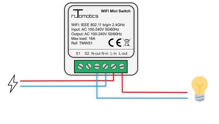
Legend:
L-in: line-in
N-in: neutral-in
L-out: line-out
N-out: neutral-out
S1: Switch wire 1
S2: switch wire 2
—: line cables
—: neutral cables
1.2. Wi-Fi switch with a physical switch installation
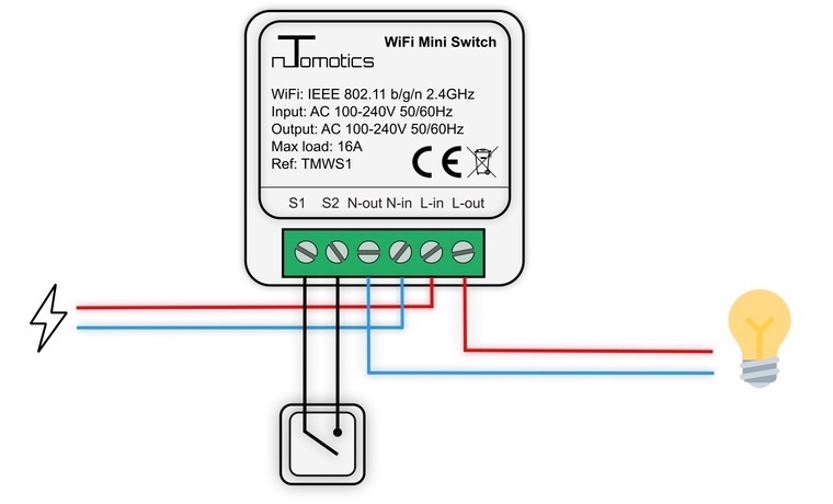
Legend:
L-in: line-in
N-in: neutral-in
L-out: line-out
N-out: neutral-out
S1: Switch wire 1
S2: switch wire 2
—: line cables
—: neutral cables
—: switch cables
1.3. Wi-Fi with a physical 2-way switch installation
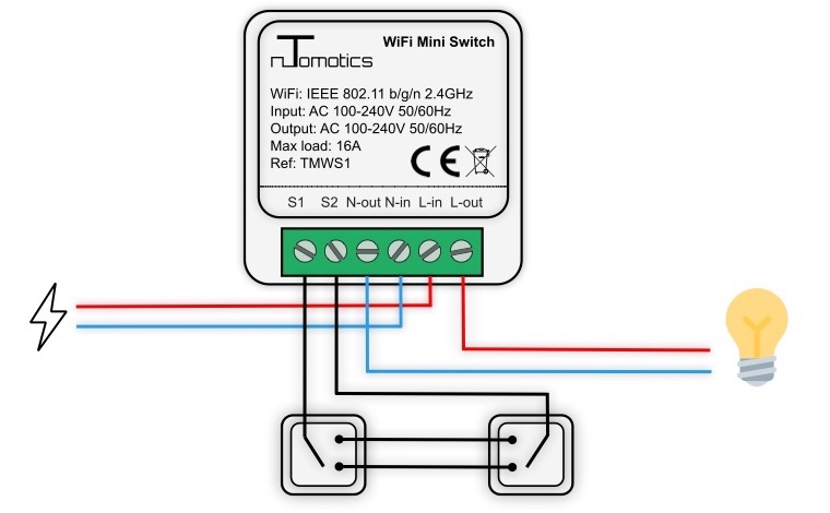
Legend:
L-in: line-in
N-in: neutral-in
L-out: line-out
N-out: neutral-out
S1: Switch wire 1
S2: switch wire 2
—: line cables
—: neutral cables
—: switch cables
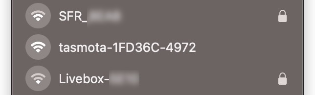
2. Software configuration
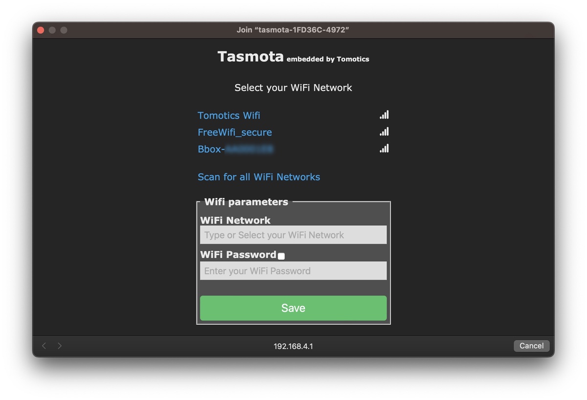
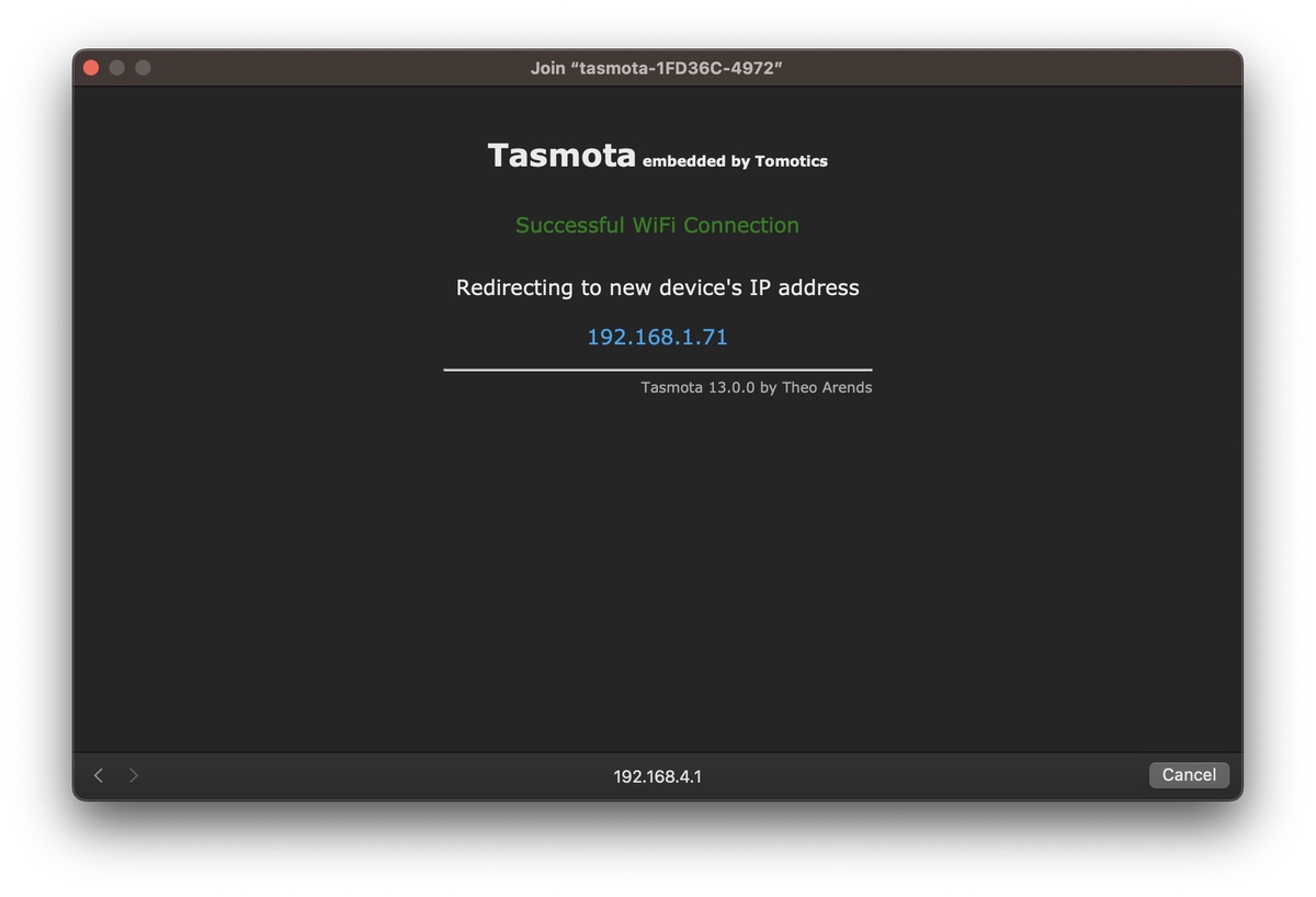
2.1 First-time start
3.Standard integration
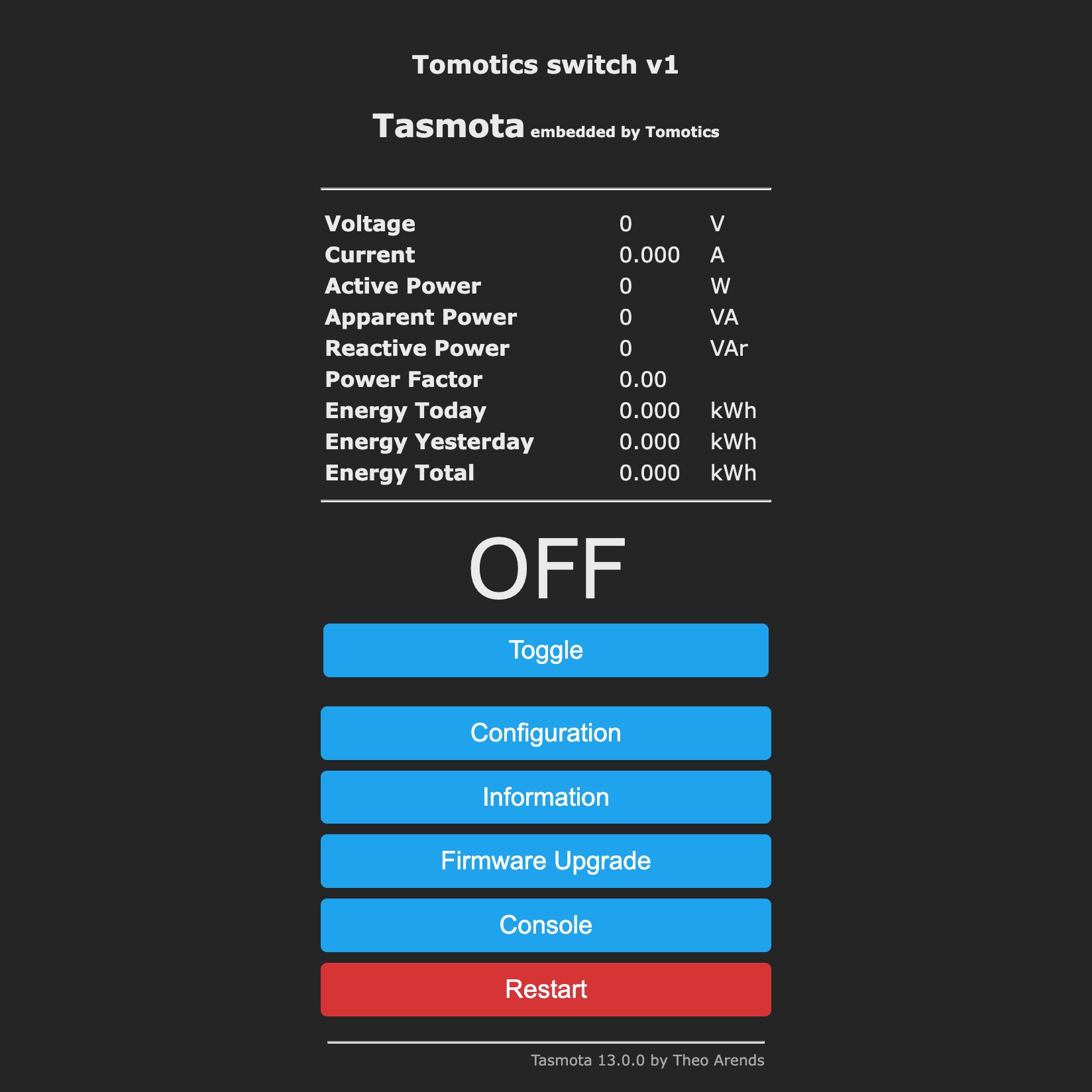
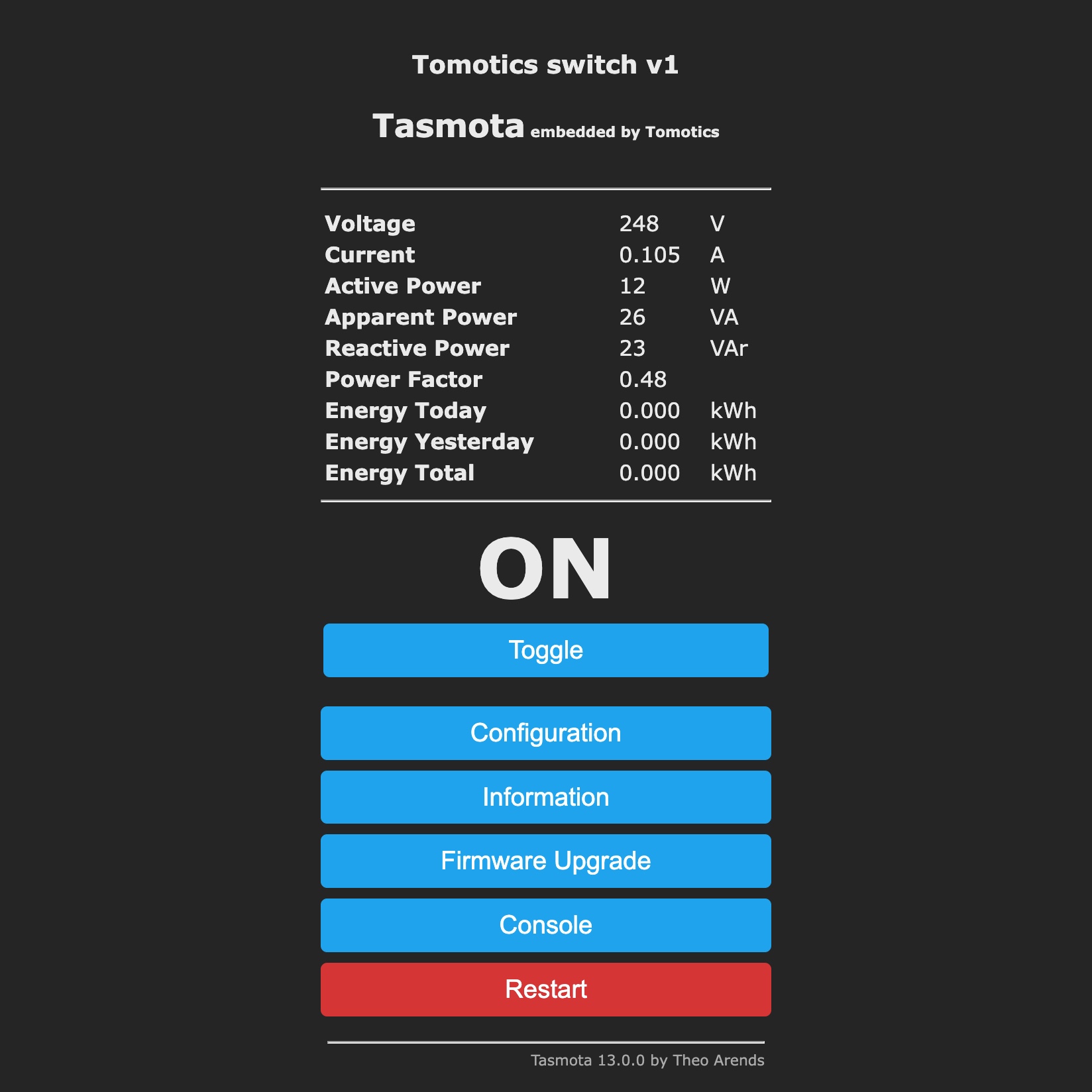
3.1 Web UI
3.2. MQTT
3.2.1 Introduction
The MQTT protocol is the optimal solution if you are using a home automation system.
You can install and configure MQTT on all open-source home automation systems (Domoticz/Jeedom/Home Assistant/...).
3.2.2 Sample configuration
To connect your Wi-Fi switch to your MQTT broker, go to the Tasmota's "Main menu" > "Configuration" > "Configure MQTT".
A sample configuration could be done as in the image below:
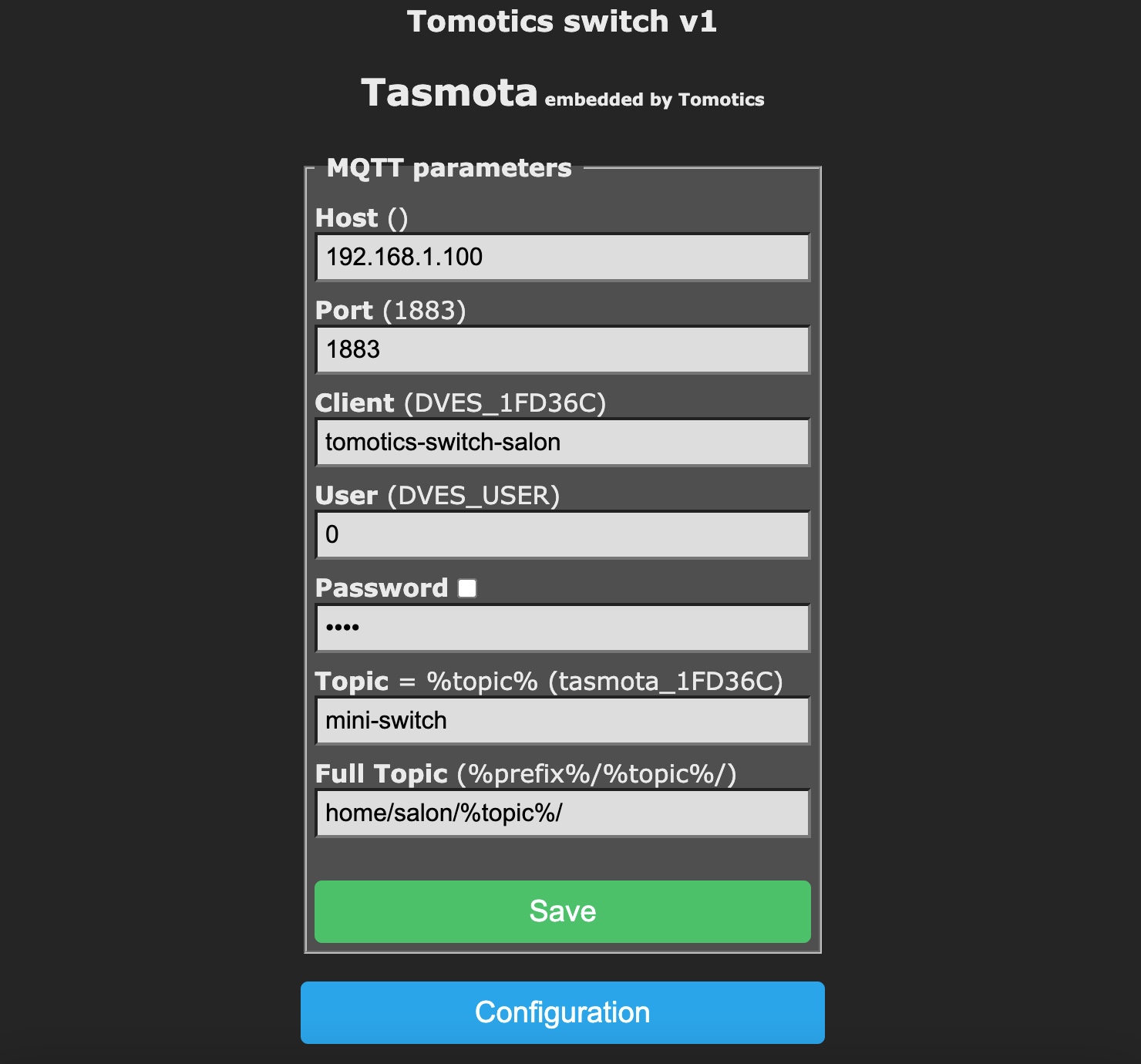
mini-switch and Full Topic: home/salon/%topic%/),home/salon/mini-switch| Topic | Value |
|---|---|
home/salon/mini-switch/POWER |
ON |
home/salon/mini-switch/SENSOR |
{ |
3.2.3 Change switch status with MQTT messages
If your main topic configuration is home/salon/mini-switch
To switch on the Wi-Fi switch you need to send the message ON in the topic home/salon/mini-switch/cmnd/POWER1 to your broker
To switch off the Wi-Fi switch you need to send the message OFF in the topic home/salon/mini-switch/cmnd/POWER1 to your broker
| Action | Topic | Value |
|---|---|---|
| Switch ON | {MAIN TOPIC}/cmnd/POWER1 |
ON |
| Switch OFF | {MAIN TOPIC}/cmnd/POWER1 |
OFF |
3.2.4 Anonymous login
Usually we connect to a MQTT broker using a login and password.
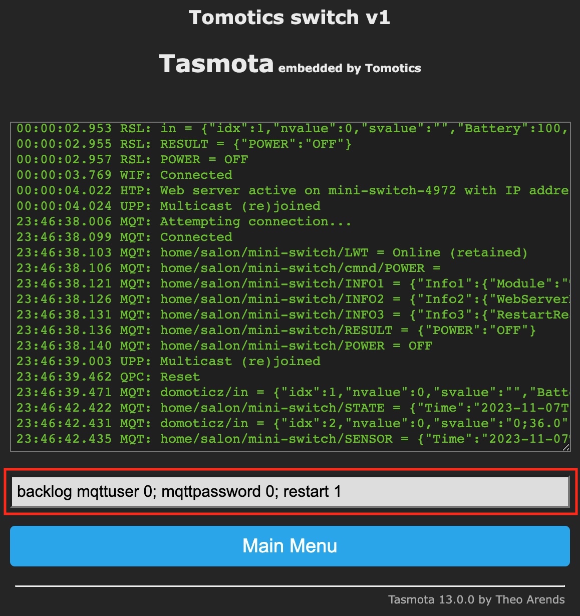
If you have not configured any user, and your MQTT broker accepts anonymous connections, you can use a specific command, because the Tasmota Web UI interface will not allow you to connect without any credentials.
From the "Main Menu" > "Console", "Enter Command" text field:
backlog mqttuser 0; mqttpassword 0; restart 1
And the press the "Enter" keyboard key:
The full MQTT configuration with Tasmota can be found on the official Tasmota Github page: https://tasmota.github.io/docs/MQTT/
3.3 HTTP calls (URLs)
| Action | Command |
|---|---|
| Power ON | http:// |
| Power OFF | http:// |
| Toggle power | http:// |
If you need to be authenticated on your HTTP requests, you will find this information on the official Tasmota page: https://tasmota.github.io/docs/Commands/#with-web-requests
4. Voice assistants integrations
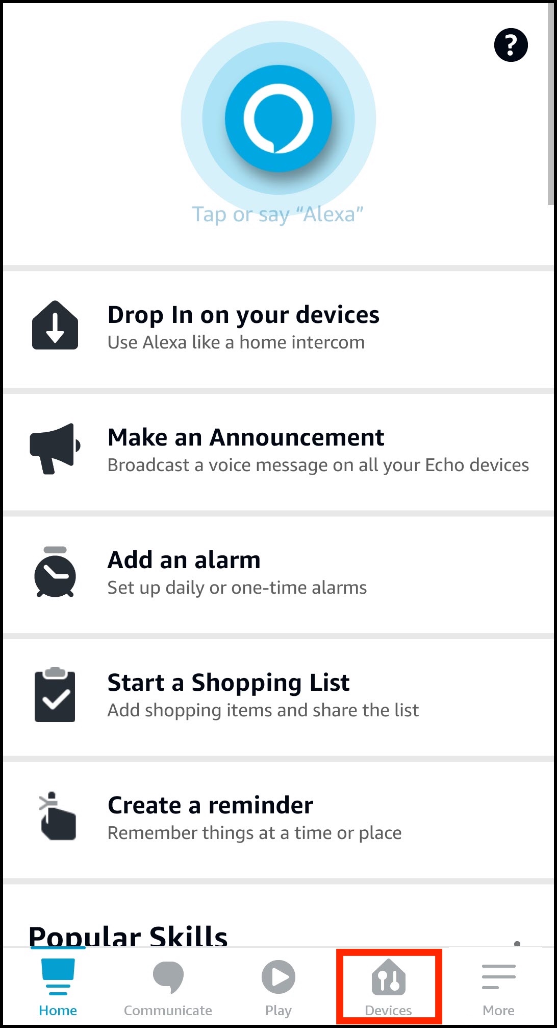
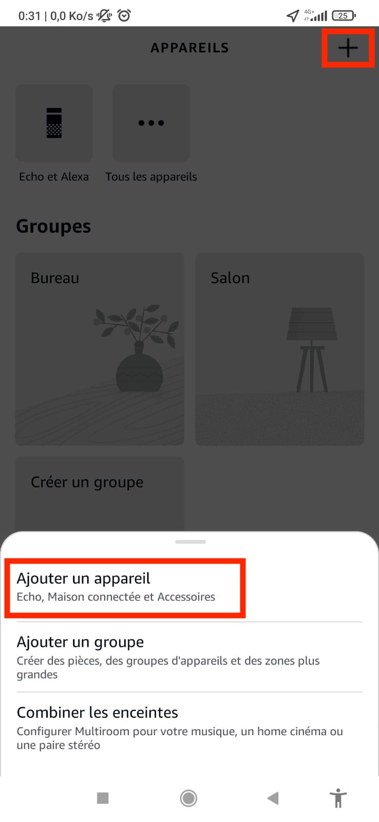
4.1 Alexa
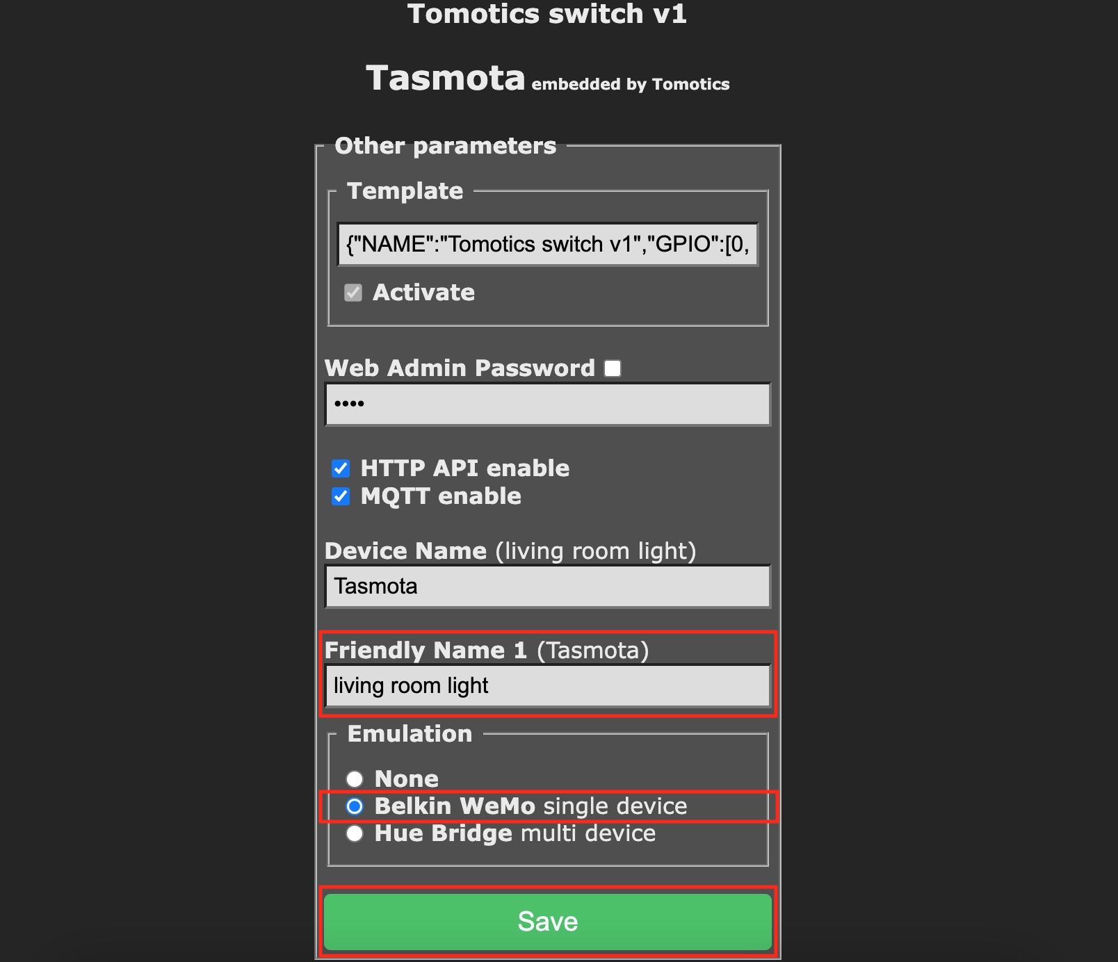
1/ Enable emulation in the Tasmota admin interface.
In the "Main menu" > "Configuration" > "Configure Other"
- select an easy-to-say name for your switch (ex: living room light)
- activate the Belkin WeMo emultation
- click on the Save button:
4.2 Google Home
To be able to communicate with a Google Home, the Wi-Fi switch needs to connected and configured with a home automation system such as Home Assistant/Jeedom/Domoticz/...
Once the connection is established you can configure a new Google Home switch in your home automation system.
5. Open home automation systems integrations
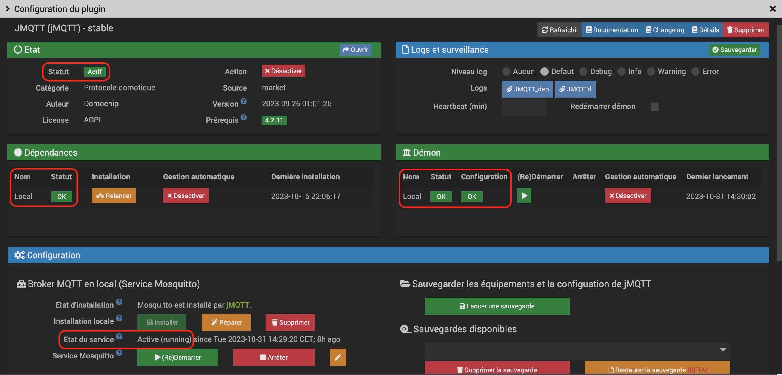
5.1 Jeedom
- the plugin must be active
- the dependencies and deamon must have the OK status
- the broker must be active and running
- uncheck "Add commands automatically"
/#ex:
home/salon/mini-switch/#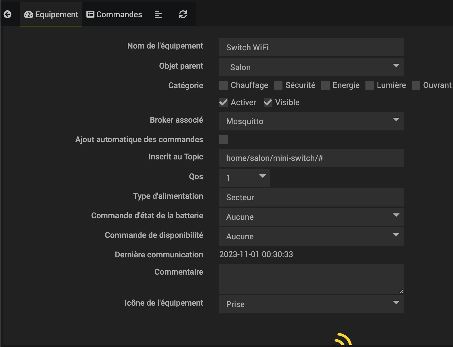
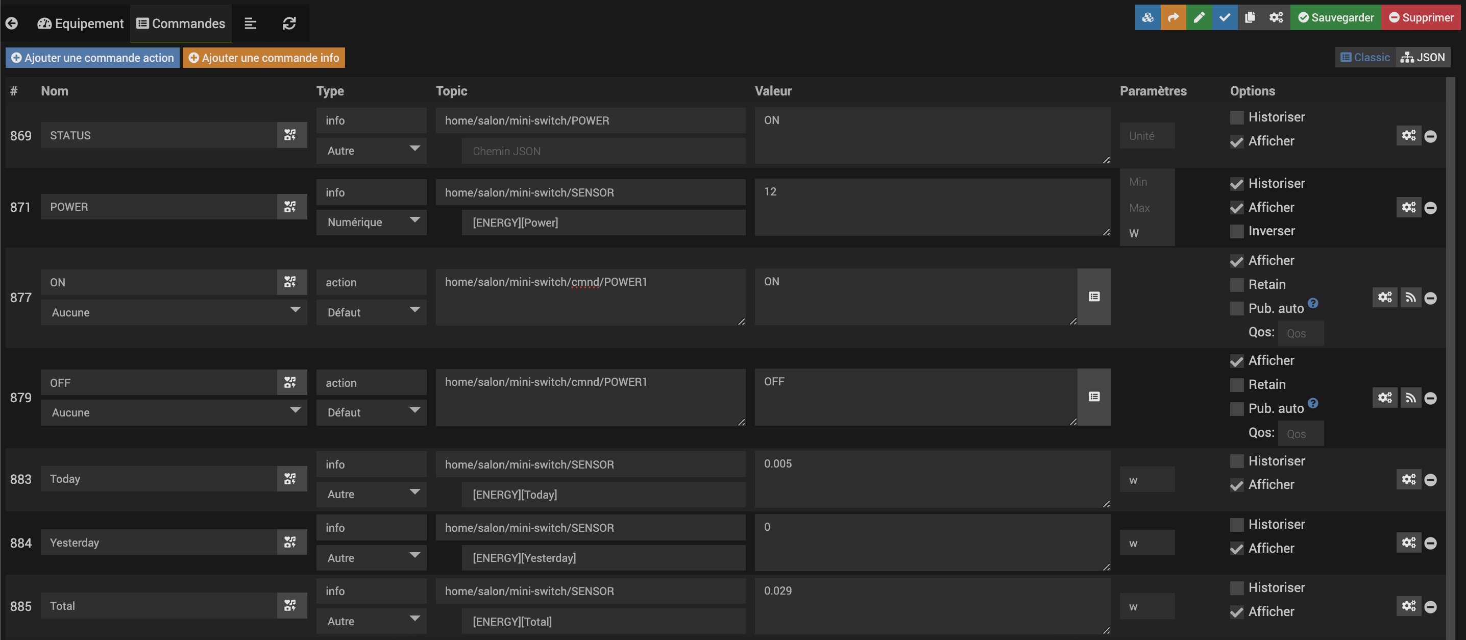
| Name | Type | Topic | Parameters | Options |
|---|---|---|---|---|
| STATUS | Info / Other | home/salon/mini-switch/POWER | Display | |
| POWER | Info / Numeric | home/salon/mini-switch/SENSOR JSON path: [ENERGY][Power] |
Unit: w | Display Historize |
| ON | Action / Default | home/salon/mini-switch/cmnd/POWER1 | Display | |
| OFF | Action / Default | home/salon/mini-switch/cmnd/POWER1 | Display | |
| Today | Info / Other | home/salon/mini-switch/SENSOR JSON path: [ENERGY][Today] |
Unit: w | Display |
| Yesterday | Info / Other | home/salon/mini-switch/SENSOR JSON path: [ENERGY][Yesterday] |
Unit: w | Display |
| Total | Info / Other | home/salon/mini-switch/SENSOR JSON path: [ENERGY][Total] |
Unit: w | Display |
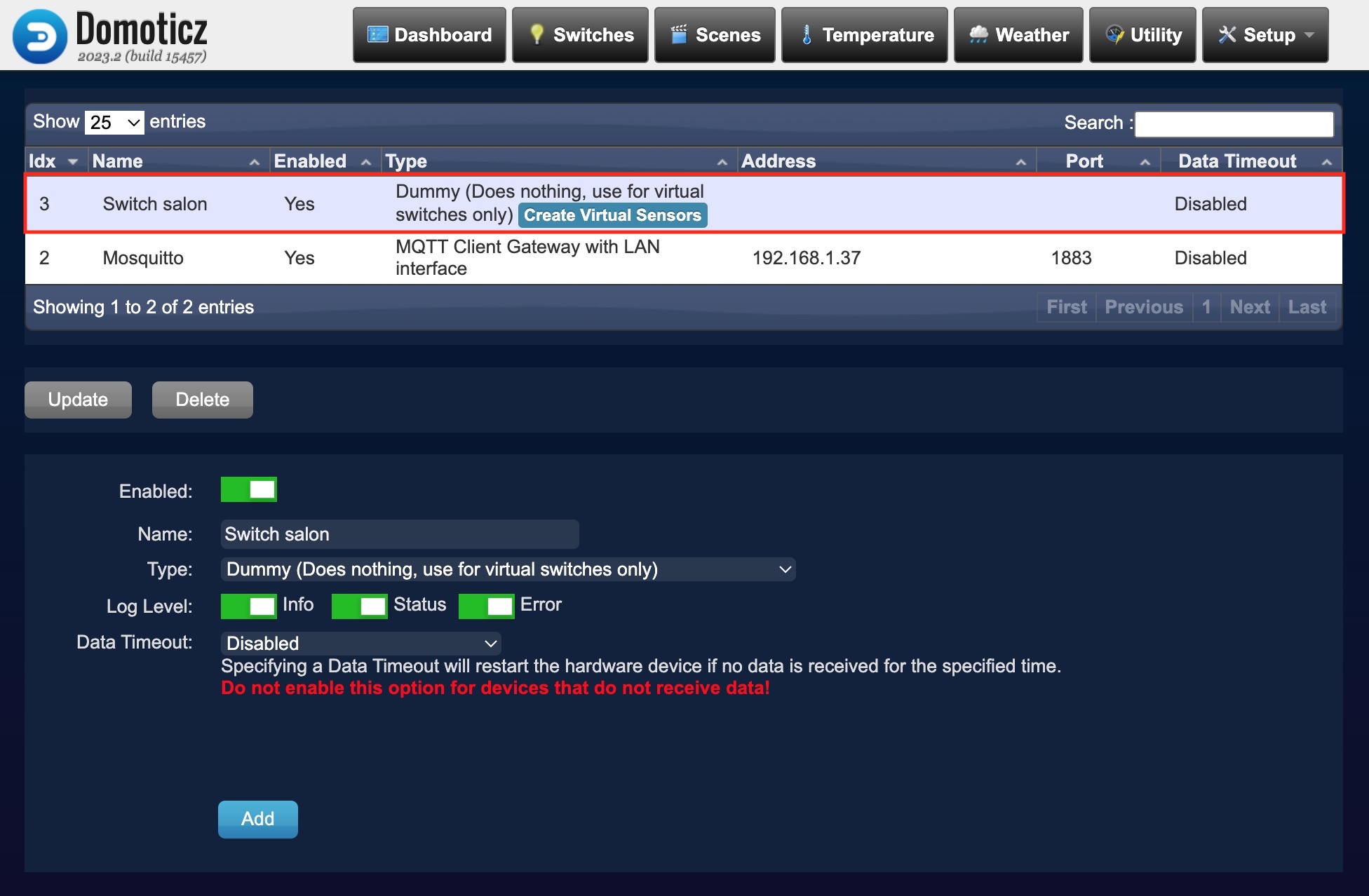
5.2 Domoticz
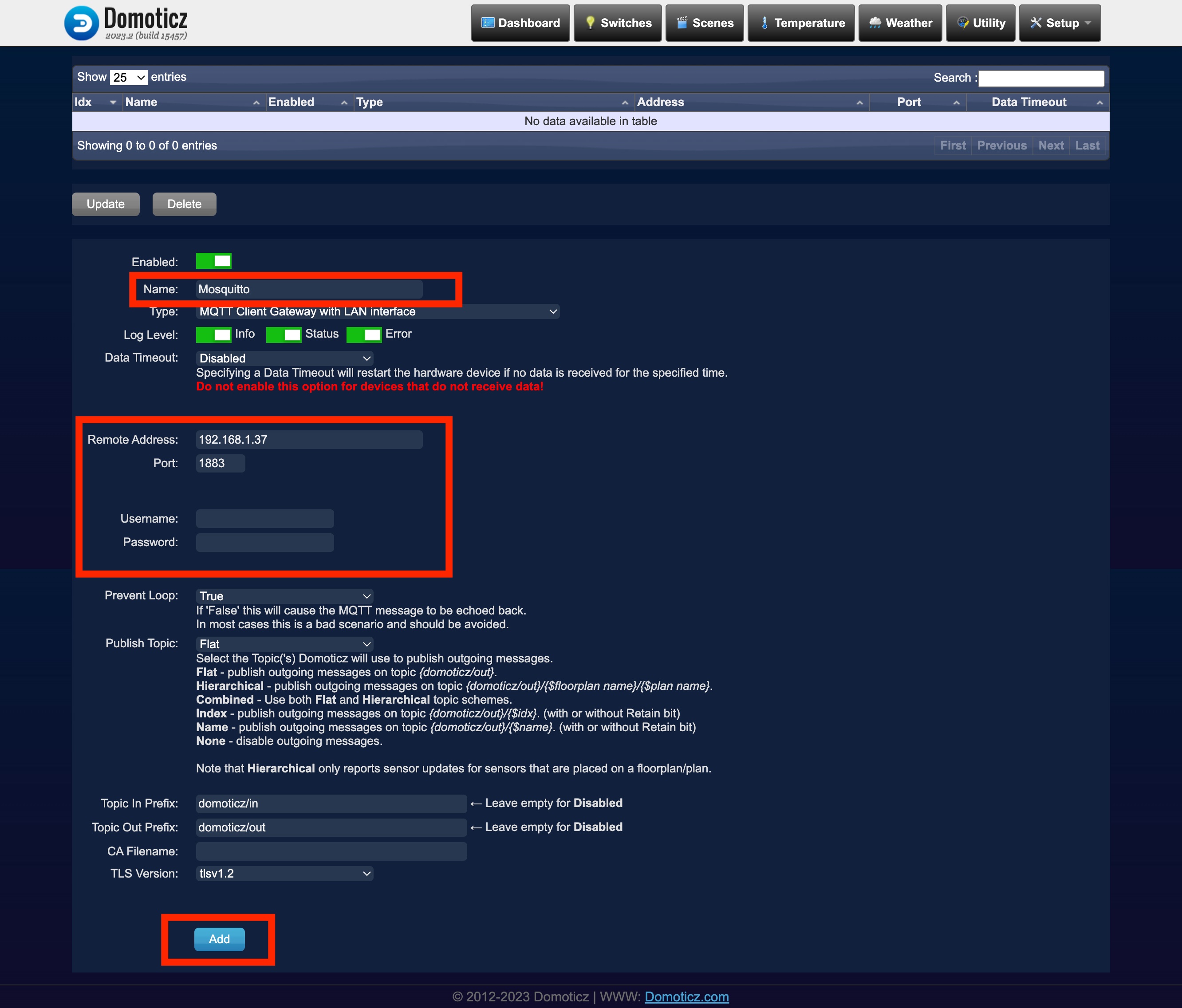
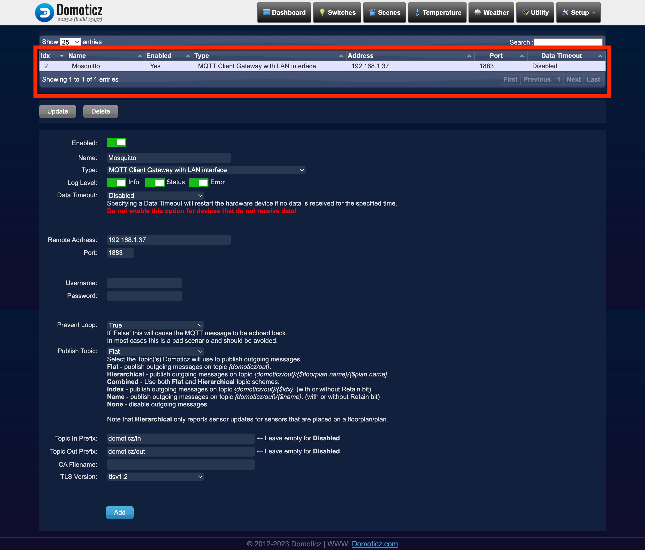
Add a MQTT interface.
In the menu "Setup" > "Hardware" add a "MQTT Client Gateway with LAN interface"
You should provide:
- a name
- the remote address (or IP address) of your MQTT broker
- the port (usually 1883)
- a username/password if necessary
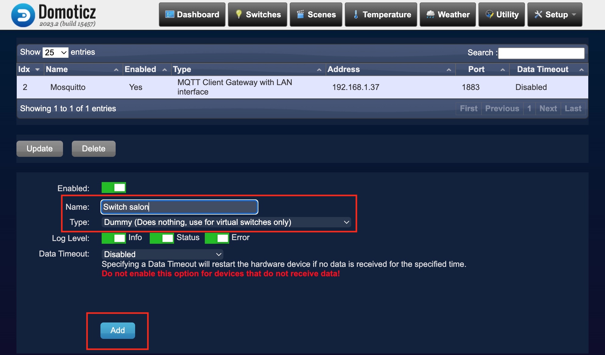
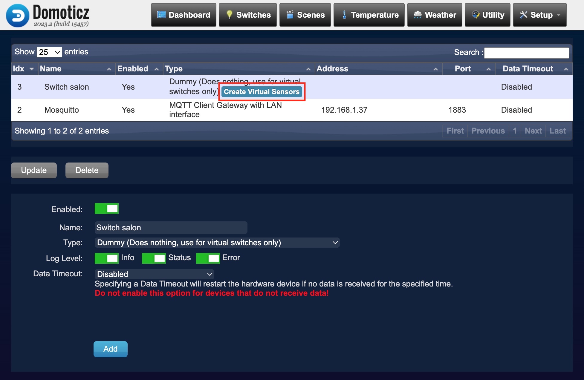
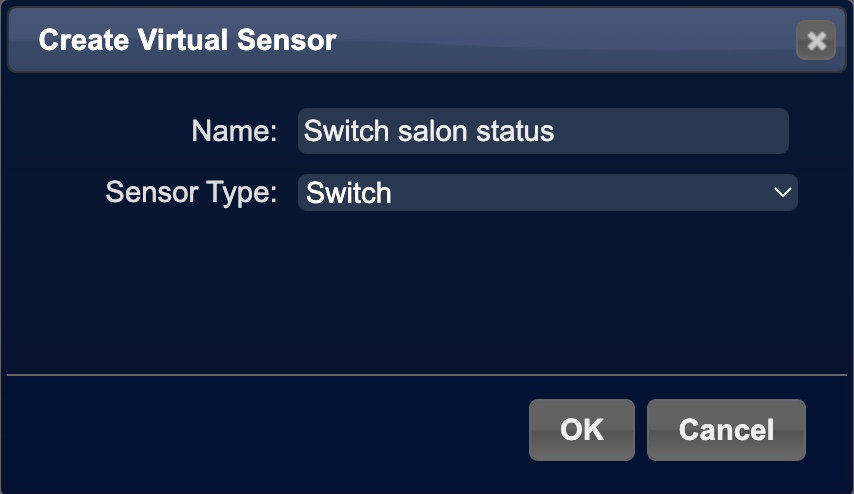
- The first virtual sensor must have a "Sensor type": Switch
- The second virtual sensor must have a "Sensor type": Electric (Instant+Counter)
 and
and 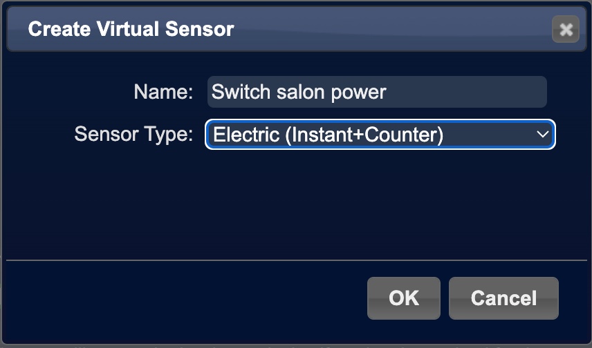
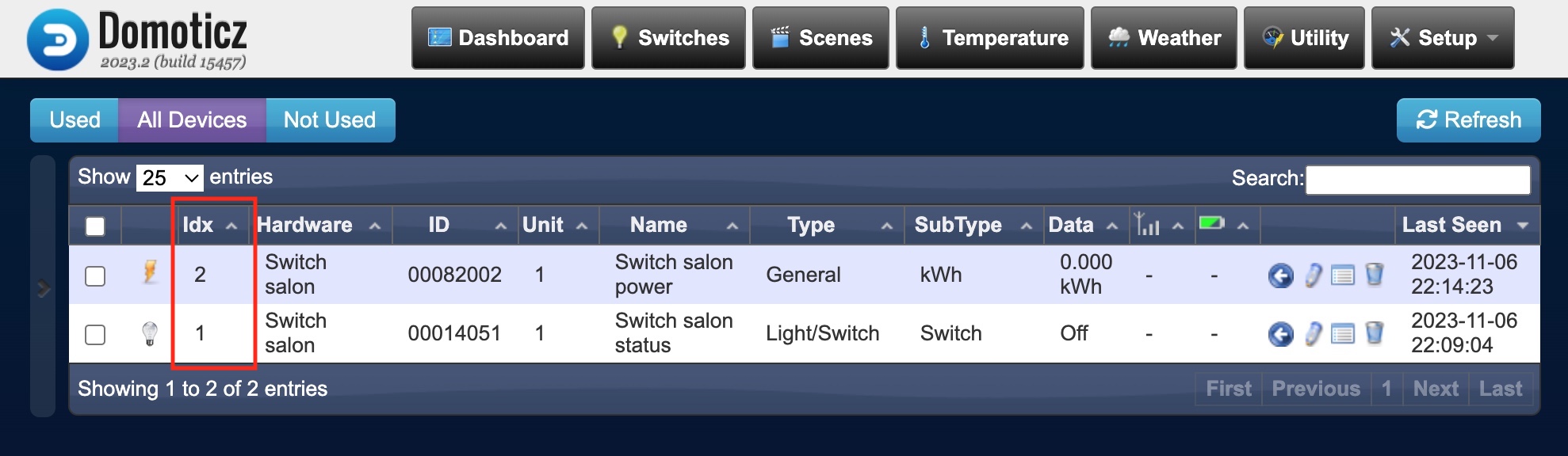
(cf. MQTT sample configuration)
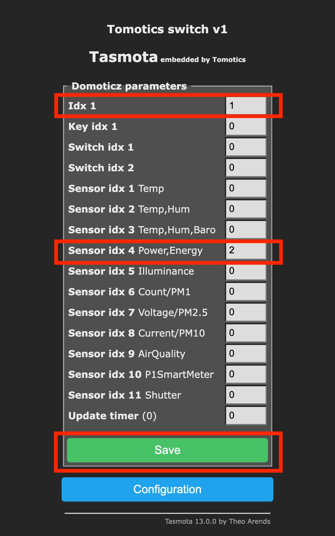
In the "Main menu" > "Configuration" > "Configure Domoticz"
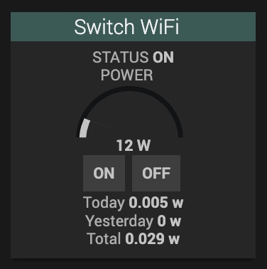
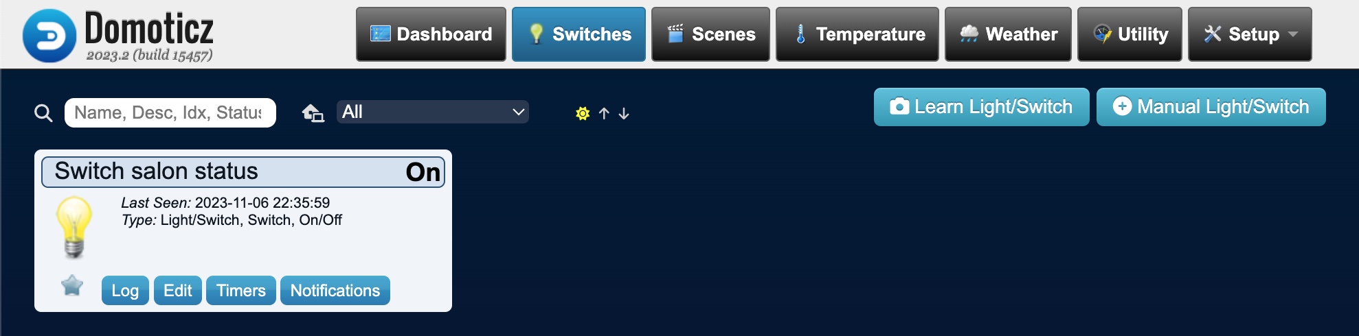
- In the menu "Switches" you must see you Wi-Fi switch,
if you click on the light bulb, it must change your switch status from on to off:
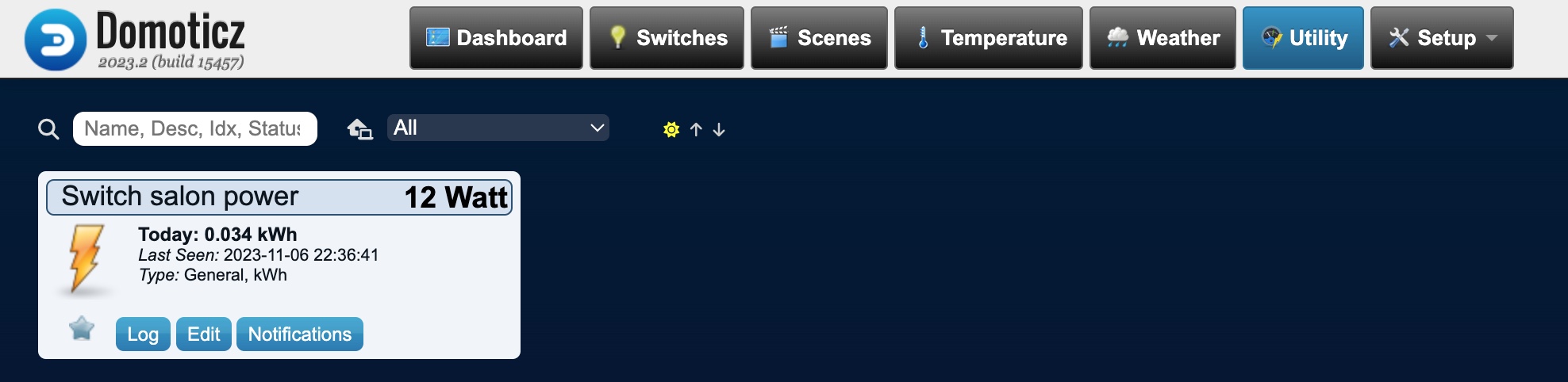
- In the menu "Utility" you must see your switch current power consumption,
(if the Wi-Fi switch is "Off" the power consumption must be equal to "0 Watt")
5.3 Home assistant
1/ (optional) Install a MQTT broker.
Home Assistant recommends to intall the Mosquitto MQTT broker add-on
The Home Assistant official documentation for the MQTT configuration can be found here.
3/ Then follow the official Tasmota devices integration documentation, which can be found here: https://www.home-assistant.io/integrations/tasmota/